Background
Due to the size and shape of our living room, I needed something special for mounting the projector. The projector will be located just behind the 15' peak of a vaulted ceiling and needs to to hang about 8' from the floor. I also did not want the projector to always be in this position as it detracts from the look of the room. What I needed was a projector lift that would lower the projector from a stored position near the ceiling to the operational position. It also needs to be remotely controlled.My solution was to build a motorized projector lift. I was inspired by designs at SVSLifts, and their prices. I nearly had a heart attack when one of their kind salespeople answered my questions about their pricing (it's in the mid-4-digit range). I decided to build my own.
The basic design uses two "scissor" arms that connect a stationary platform mounted at the ceiling with a mobile platform mounted at the bottom of the arms. The mobile platform is actually suspended by 3/16" vinyl coated cable from a motorized drum mounted on the top platform. By turning the motor on, the drum collects or pays out (depending on the direction of the motor) cable and raises or lowers the platform. The scissor arms guide and stabilize the platform.
All the metal parts used are aluminum stock bought at Home Depot. I had
the parts for the scissor arms professionally milled so they fit correctly.
All the remaining metal parts I milled myself using a bandsaw, drill press,
and various hand tools. All the wood parts are 3/4" birch plywood,
milled by myself.
You can see some screenshots of the plans for the aluminum arms
here and
here.
The lift and projector will share a 20 amp circuit with the screen, and
have a 500VA APC UPS to provide clean power for the projector.
This part of the Home Theater Project is done!
The lift works exactly as I intended and
is able to accuratly position the projector with a high degree of
repeatability. It takes about 25 seconds to fully retract or extend the lift.
It's a little more noisy than I would prefer, but it doesn't operate while
watching movies, of course. All in all, I'm very happy.
Mechanical
 Here's a basic cross-section of the lift in the closed position. The
projector is actually mounted underneath a platform that is mounted to the
bottom platform, thereby emulating a ceiling mount.
Here's a basic cross-section of the lift in the closed position. The
projector is actually mounted underneath a platform that is mounted to the
bottom platform, thereby emulating a ceiling mount.
 Since the scissor arms move in relation to each other, it's important
to allow them to move smoothly and silently; I have no desire to hear the
screech of metal as the projector moves into position. To accomplish this
I used a a series of nylon washers and spacers so that no two metal pieces
are in direct contact with each other.
Since the scissor arms move in relation to each other, it's important
to allow them to move smoothly and silently; I have no desire to hear the
screech of metal as the projector moves into position. To accomplish this
I used a a series of nylon washers and spacers so that no two metal pieces
are in direct contact with each other.
 The first motor I used for the lift was an old garage door motor I reclaimed
after installing a new one for my mother-in-law. I think it was about 1/3HP.
It had a 7 tooth sprocket driven by a worm gear.
I left the motor and worm drive mounted to the original housing and trimmed
off all the electronics. I made the aluminum diagonal braces from flat stock.
The whole thing was mounted on a movable platform for the purpose of tensioning
the chain. While this whole arrangement worked well, I replaced the motor later.
The first motor I used for the lift was an old garage door motor I reclaimed
after installing a new one for my mother-in-law. I think it was about 1/3HP.
It had a 7 tooth sprocket driven by a worm gear.
I left the motor and worm drive mounted to the original housing and trimmed
off all the electronics. I made the aluminum diagonal braces from flat stock.
The whole thing was mounted on a movable platform for the purpose of tensioning
the chain. While this whole arrangement worked well, I replaced the motor later.
 While looking on eBay for motor parts for the screen
part of this project,
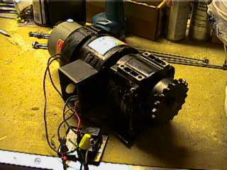
I came across a good deal for a different motor. The new motor had one major
advantage; it took up less vertical space which would allow me to mount the
lift closer to the ceiling. It also had a lot more power and was built
much more ruggedly. Since it's a parallel shaft gear motor, It needs a brake,
which it came with. I had to add a sprocket, but a quick stop at Graingers
took care of that. Since the sprockets Graingers carries take a larger
chain than the garage door opener, I also picked up a new chain and a
matching sprocket for the cable drum. The motor is shown unmounted, but
it mounts to a slip plate just like the old motor.
While looking on eBay for motor parts for the screen
part of this project,
I came across a good deal for a different motor. The new motor had one major
advantage; it took up less vertical space which would allow me to mount the
lift closer to the ceiling. It also had a lot more power and was built
much more ruggedly. Since it's a parallel shaft gear motor, It needs a brake,
which it came with. I had to add a sprocket, but a quick stop at Graingers
took care of that. Since the sprockets Graingers carries take a larger
chain than the garage door opener, I also picked up a new chain and a
matching sprocket for the cable drum. The motor is shown unmounted, but
it mounts to a slip plate just like the old motor.
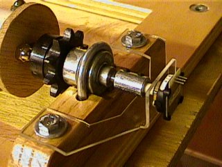
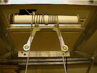
 The cable drum is an assembly I designed and built from 1 1/2" PVC pipe,
1/4" threaded rod, and oak (i.e., wood) hubs.
The drum contains 3 oak hubs which hold 2 threaded rods that run the length
of the drum in parallel. These rods stiffen the PVC pipe while there
is also shorter threaded rods passing through the additional holes in the
oak hubs, threaded into the steel axle.
The cable drum is an assembly I designed and built from 1 1/2" PVC pipe,
1/4" threaded rod, and oak (i.e., wood) hubs.
The drum contains 3 oak hubs which hold 2 threaded rods that run the length
of the drum in parallel. These rods stiffen the PVC pipe while there
is also shorter threaded rods passing through the additional holes in the
oak hubs, threaded into the steel axle.
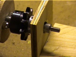
 The drum rotates on a solid 1/2" steel rod (the axle) which passes through
a homemade pillow block bearing attached to the platform on each end.
A sprocket is also mounted to the axle rod using a set screw. On one end of
the axle I've attached a rotary quadrature encoder with a custom
plexiglass mount. The encoder feeds the custom electronics (see below)
with the drum's rotational position.
The picture shows the old sprocket and motor and doesn't show the sensor
or its plexiglass mount.
The drum rotates on a solid 1/2" steel rod (the axle) which passes through
a homemade pillow block bearing attached to the platform on each end.
A sprocket is also mounted to the axle rod using a set screw. On one end of
the axle I've attached a rotary quadrature encoder with a custom
plexiglass mount. The encoder feeds the custom electronics (see below)
with the drum's rotational position.
The picture shows the old sprocket and motor and doesn't show the sensor
or its plexiglass mount.
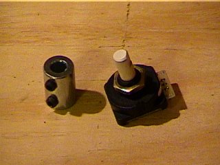 The sensor shaft is only 1/4" and is attached to the axle with a steel
shaft coupler, also from Graingers.
The sensor shaft is only 1/4" and is attached to the axle with a steel
shaft coupler, also from Graingers.
 Since the axle is 1/2" and the sensor is 1/4", I had to mill the end of the
axle down to size using a homemade jig and an angle grinder. The jig is made
of scrap plywood and 2x4, my 1/2" Milwaukee drill, and some clamps.
The assembled drum is mounted in the drill chuck and the drill is
turned on using a piece of velcro around the trigger. I uses the angle
grinder on the end of the spinning axle sticking out on the right.
Since the axle is 1/2" and the sensor is 1/4", I had to mill the end of the
axle down to size using a homemade jig and an angle grinder. The jig is made
of scrap plywood and 2x4, my 1/2" Milwaukee drill, and some clamps.
The assembled drum is mounted in the drill chuck and the drill is
turned on using a piece of velcro around the trigger. I uses the angle
grinder on the end of the spinning axle sticking out on the right.
 Here's the finished work. I also used the grinder to make a flat on the axle
so the shaft coupler would have something to hold against.
It worked surprisingly well.
Here's the finished work. I also used the grinder to make a flat on the axle
so the shaft coupler would have something to hold against.
It worked surprisingly well.
 This is what the sensor and its plexiglass mount look like when mounted to
the axle and platform.
This is what the sensor and its plexiglass mount look like when mounted to
the axle and platform.
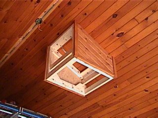
 Here's the lift mounted to my garage/workshop ceiling. It's in the "up"
position. While hard to see, the projector will mount under the piece of
plywood above the bottom platform (it's inside the arms). That piece of plywood
acts as the "ceiling" as far as the projector is concerned.
Here's the lift mounted to my garage/workshop ceiling. It's in the "up"
position. While hard to see, the projector will mount under the piece of
plywood above the bottom platform (it's inside the arms). That piece of plywood
acts as the "ceiling" as far as the projector is concerned.
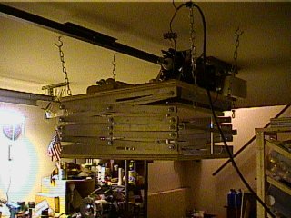 Another picture in the up position.
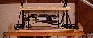
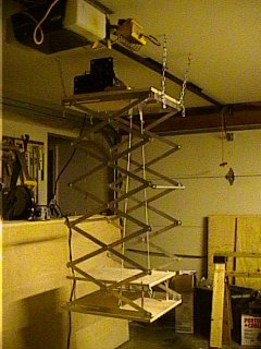 Here's what the lift looks like in the down position. It can actually extend 8'
down, but my garage ceiling isn't that high.
Here's what the lift looks like in the down position. It can actually extend 8'
down, but my garage ceiling isn't that high.
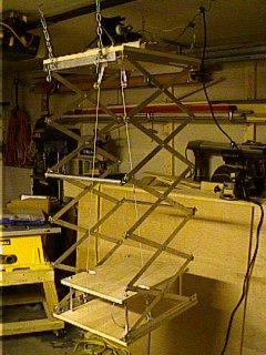 Another "down" picture.
 This is a shot of a late add-on to correct a problem I was hoping wouldn't
be one. The cable is supposed to wrap nicely on the drum as the lift is raised
but it has a tendency to spread out and ends up winding off the ends of the
drum before the lift is fully raised. This device tensions the cable and
keeps it winding more tightly. The round bearings/guides are actually
patio door wheels made of solid brass that I picked up at Home Depot.
This is a shot of a late add-on to correct a problem I was hoping wouldn't
be one. The cable is supposed to wrap nicely on the drum as the lift is raised
but it has a tendency to spread out and ends up winding off the ends of the
drum before the lift is fully raised. This device tensions the cable and
keeps it winding more tightly. The round bearings/guides are actually
patio door wheels made of solid brass that I picked up at Home Depot.
 This is the top platform and motor mount slip plate after disassembly
and 3 coats of clear gloss polyurathane.
The black stripes are pieces of anti-slip stair
tape made by 3M. It's like sandpaper with adhesive. The motor mount is
upside down for the picture, but will be turned over so the tape meets the
tape on the platform. This ensures the mount doesn't actually slip after it's
tightened down with bolts after the chain has been tensioned.
This is the top platform and motor mount slip plate after disassembly
and 3 coats of clear gloss polyurathane.
The black stripes are pieces of anti-slip stair
tape made by 3M. It's like sandpaper with adhesive. The motor mount is
upside down for the picture, but will be turned over so the tape meets the
tape on the platform. This ensures the mount doesn't actually slip after it's
tightened down with bolts after the chain has been tensioned.
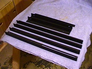 These are some of the aluminum parts after painting. I first cleaned each
piece with Comet Aluminum cleaner, then primed, then painted with flat
black enamal. The result is a very nice, durable finish.
These are some of the aluminum parts after painting. I first cleaned each
piece with Comet Aluminum cleaner, then primed, then painted with flat
black enamal. The result is a very nice, durable finish.
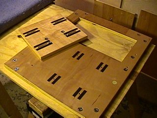
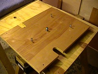 Here's the part of the lift the projector actually mounts to (almost). This
is the top view. The 3 bolts sticking up pass through t-nuts on the other
side and are tipped with rubbery caps. They apply pressure to a 1/4" plexiglass
panel that is attached to the projector and allow it to be turned, tilted,
and locked in position. The fourth bolt holds the plexiglass to the
wood with a spring to provide tension.
Here's the part of the lift the projector actually mounts to (almost). This
is the top view. The 3 bolts sticking up pass through t-nuts on the other
side and are tipped with rubbery caps. They apply pressure to a 1/4" plexiglass
panel that is attached to the projector and allow it to be turned, tilted,
and locked in position. The fourth bolt holds the plexiglass to the
wood with a spring to provide tension.
 Here's the plexiglass panel still with it's paper on. When the paper is removed,
it will be clear. The "U" shaped cutouts allow for the cable as it passes
on its way to the eye-bolts on the lower platform (not pictured).
Here's the plexiglass panel still with it's paper on. When the paper is removed,
it will be clear. The "U" shaped cutouts allow for the cable as it passes
on its way to the eye-bolts on the lower platform (not pictured).
Electrical
This part of the project relies on a
motor controller, the same design as used for the screen.
Enclosure
Due to the width of the lift (20") and the spacing of the roof trusses in my
living room (16"), I couldn't easily mount the projector and lift in the
ceiling. I decided to surface mount it and live with the bump on the ceiling.
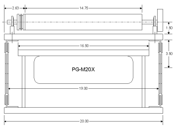
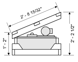 After a number of designs I settled on a basic box, angled to meet the
ceiling. This is a cross-section of the inside of the enclosure. The
gray areas represent the lift including the drum and motor. The frame is
made of 2 parts that are connected by the plywood "skin" of the enclosure.
After a number of designs I settled on a basic box, angled to meet the
ceiling. This is a cross-section of the inside of the enclosure. The
gray areas represent the lift including the drum and motor. The frame is
made of 2 parts that are connected by the plywood "skin" of the enclosure.
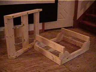 The enclosure's frame is made of 2x4 and 2x6, screwed, glued, and bolted
together. It's designed to be dis/assembled for ease of mounting and
maintenance. You can also see the aluminum frame for the UPS mount.
In case you're wondering, yes, my living room is currently bare plywood.
Another one of my projects is installing in-floor radiant heating next
summer, but I digress.
The enclosure's frame is made of 2x4 and 2x6, screwed, glued, and bolted
together. It's designed to be dis/assembled for ease of mounting and
maintenance. You can also see the aluminum frame for the UPS mount.
In case you're wondering, yes, my living room is currently bare plywood.
Another one of my projects is installing in-floor radiant heating next
summer, but I digress.
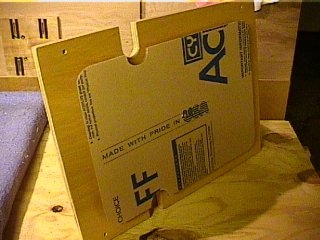
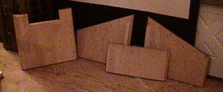 The frame is skinned in 3/4" AC plywood. The side panels are structural as
they provide the only connection between the top and bottom parts of the
frame.
The frame is skinned in 3/4" AC plywood. The side panels are structural as
they provide the only connection between the top and bottom parts of the
frame.
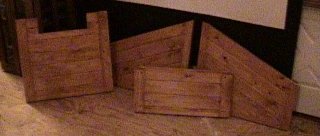 The other side (outside) of the plywood skin is finished in 3/4" tongue
and groove knotty pine, stained to match (almost) the ceiling.
The other side (outside) of the plywood skin is finished in 3/4" tongue
and groove knotty pine, stained to match (almost) the ceiling.
 When assembled, the enclosure weighs almost 100 lbs. It's a good thing it
can be taken apart for mounting. It will be attached to the ceiling trusses
using 6 - 3/8" x 6" lag bolts.
The picture shows the view of the front
of the enclosure (the side the projector will project out from). This side
is removable after the enclosure is installed,
allowing access to the inside for inspection
and repair (hopefully not the latter).
The notch
in the top is for a wire chase that I'll build when the enclosure is mounted
on the ceiling. The chase will contain the video cable, serial control cable,
projector control cable, and power.
When assembled, the enclosure weighs almost 100 lbs. It's a good thing it
can be taken apart for mounting. It will be attached to the ceiling trusses
using 6 - 3/8" x 6" lag bolts.
The picture shows the view of the front
of the enclosure (the side the projector will project out from). This side
is removable after the enclosure is installed,
allowing access to the inside for inspection
and repair (hopefully not the latter).
The notch
in the top is for a wire chase that I'll build when the enclosure is mounted
on the ceiling. The chase will contain the video cable, serial control cable,
projector control cable, and power.
Installation
Installation of the lift began on October 25 and was completed November 9.
Most of that time was actually spent wiring.
Here are the pictures and chain of events.
 This is the new motor mounted on the lift platform. You can also see the
position sensor wire in the lower right. After final installation, the
motor mount will need to be adjusted to tension the chain.
This is the new motor mounted on the lift platform. You can also see the
position sensor wire in the lower right. After final installation, the
motor mount will need to be adjusted to tension the chain.
 The top of the frame is mounted to the ceiling with 6 lag bolts. You can
see the aluminum brackets that will hold the UPS. You can also see
where the old ceiling fan was mounted. That box will be removed and the
hole will be reused for the 2" flexible conduit that will house the
video and signal cables. There will a wire chase that matches the enclosure
between the hole and the front of the enclosure.
The top of the frame is mounted to the ceiling with 6 lag bolts. You can
see the aluminum brackets that will hold the UPS. You can also see
where the old ceiling fan was mounted. That box will be removed and the
hole will be reused for the 2" flexible conduit that will house the
video and signal cables. There will a wire chase that matches the enclosure
between the hole and the front of the enclosure.
 The side panels and bottom frame have been mounted.
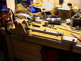
 The bottom trim frame and main lift platform have been mounted.
The picture also shows the change
in daylight since the previous picture. Ther top of the 10' scaffold is
also visible.
The bottom trim frame and main lift platform have been mounted.
The picture also shows the change
in daylight since the previous picture. Ther top of the 10' scaffold is
also visible.
 This is another angle of the same setup of the previous picture.
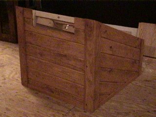
 All the main lift components have been installed and the bottom enclosure face
has been mounted. The bottom platform is suspended by a rope, barely visible
in this picture.
All the main lift components have been installed and the bottom enclosure face
has been mounted. The bottom platform is suspended by a rope, barely visible
in this picture.
 Here's a picture of the wiring inside the enclosure. It's hard to see in this
light but the UPS is mounted at the top, the motor controller on the left,
and the power outlet just to the right of that. There are bundles of wire
tied wires running between the controller and the motor, and all the
sensor wires are clamped down with nylon wire holders.
Here's a picture of the wiring inside the enclosure. It's hard to see in this
light but the UPS is mounted at the top, the motor controller on the left,
and the power outlet just to the right of that. There are bundles of wire
tied wires running between the controller and the motor, and all the
sensor wires are clamped down with nylon wire holders.
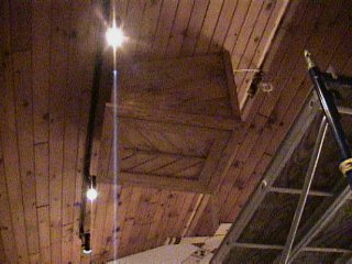 The lift has been wired and is able to move up and down. This is the fully
closed position. I wired the electronics and power 3 times before I was
happy with how it looked.
The lift has been wired and is able to move up and down. This is the fully
closed position. I wired the electronics and power 3 times before I was
happy with how it looked.
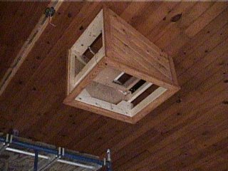
 Here, all the enclosure sides are installed as well as the wire chase.
Inside the chase, the video cable, serial cable, and power cable
are routed between the enclosure and the existing hole in the ceiling.
You can also see the new track lighting and ceiling fans.
Here, all the enclosure sides are installed as well as the wire chase.
Inside the chase, the video cable, serial cable, and power cable
are routed between the enclosure and the existing hole in the ceiling.
You can also see the new track lighting and ceiling fans.
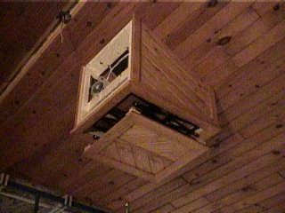
 Here's the projector mounted in its new home. You can plainly see the corner
guide blocks on the platform which align the platform and guide it into the
upper enclosure when the lift is closed.
Here's the projector mounted in its new home. You can plainly see the corner
guide blocks on the platform which align the platform and guide it into the
upper enclosure when the lift is closed.
 Here's another picture taken in front of the projector. You can see the
video cable of the left side. It's housed in 1/2" flexible tubing that is
wire tied up the right hand side of the lift arms. Power is wire tired down
the left side of the lift arms.
Here's another picture taken in front of the projector. You can see the
video cable of the left side. It's housed in 1/2" flexible tubing that is
wire tied up the right hand side of the lift arms. Power is wire tired down
the left side of the lift arms.
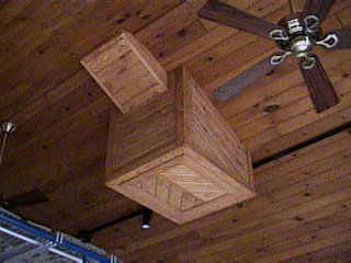
 Here's the lift in the normal operating position. It can lower another foot
for maintenence, if necessary, but I can easily reach the projector in this
position when standing on a ladder.
Here's the lift in the normal operating position. It can lower another foot
for maintenence, if necessary, but I can easily reach the projector in this
position when standing on a ladder.